
12.04.2023
C-frame: cut-outs allow for near-linear bending under load
ECKOLD know-how in C-frame design
At first glance, C-frames used in ECKOLD systems for clinching self-piercing riveting and extrusion embossing are rather inconspicuous machines. However, they are packed with know-how and advanced technology. One special characteristic of our C-frame machines is the parallel, linear bending of the frame back when under load. What this means is best explained with the example of the letter "C". Let us assume that a force is acting on the two ends of the letter at the gap. If the end faces at the gap are parallel to each and in a horizontal position, a force on these faces would lead to a counterforce deforming the gap as well as the shape of the letter in general. As a result, parallelism and angularity would be lost.
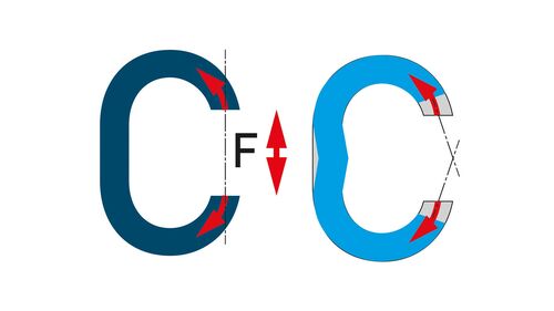
If our frames for clinching, self-piercing riveting or extrusion embossing would behave like the "C" shape in the above example, their back would need to be heavily reinforced. As a consequence, it would not be possible to handle the frames in any efficient way, and certainly not with an industrial robot.
There are however technical solutions that prevent deformation of the C-frame. The bending behaviour of the frame can be changed by making cut-outs in the back of the frame.
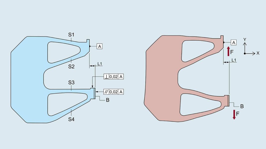
Let us explain the principle using the example of an extrusion embossing frame. The same principle applies of course to all above ECKOLD techniques and equipment that include C-frames operated by industrial robots, installed in larger machines or run as stand-alone devices.

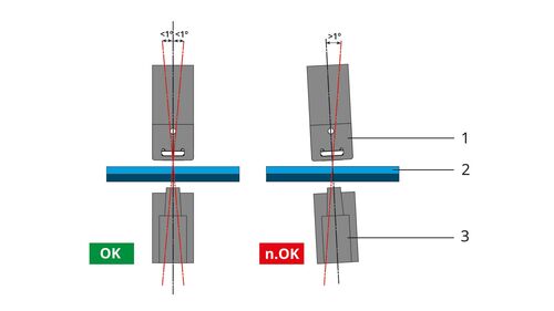
Thanks to the special shape of the struts (S1 – S4) and cut-outs, the C-frame responds to a force F applied at the tools in such a manner that dimension L1 is maintained and the strut end face B remains parallel to the reference plane A, and perpendicular to the applied force.
This means that the strut end face B moves parallel to the force direction Y, without shifting or angular error. The strut end face B is shifted parallel to the strut end face A and in the direction of the force.
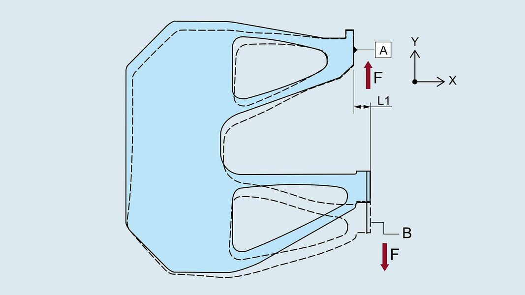
The behaviour of the frame under load becomes even clearer when the two frame diagrams (with and without load) are superimposed.
The bending behaviour described above is the result of the special design of the frame with cut-outs and struts (here: S1 – S4). To achieve the desired behaviour, the frame must feature at least 2 cut-outs, which automatically results in a design with struts. To reduce the weight of the frame, it is possible to include additional cut-outs or recesses in the back of the frame. The clip below illustrates again the principle of the design and its effect on the bending behaviour of the C-frame.
The design of this type of C-frame is made possible with advanced design and computing technology for the structural-mechanical calculation of machine components, taking into account stress and deformation properties (for instance with the Finite Element Method / FEM). Such calculations also enable our engineers to achieve other improvements, such as topology optimisation for weight reduction.
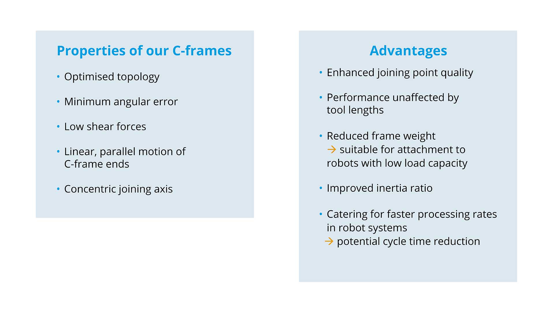
The design process involving structural-mechanical calculations is highly complex. To find optimised solutions, we employ staff with advanced engineering skills and extensive experience. Thanks to our innovative approach, we can offer you C-frames with the following properties and advantages:
Successful launch at BlechExpo 2019
At the BlechExpo 2019 in Stuttgart, Germany, we successfully launched our new servo-motor driven clinching system 2. This new product features many innovative properties such as topology-optimised clinching frames with linear bending behaviour and full integration of ECKOLD VISU, our visualisation solution for process parameterisation, monitoring and documentation.
Modern requirements regarding machine design and machining accuracy
In order to meet the quality requirements for products, manufacturers must meet minimum quality standards that often concern many different aspects and properties of the product. These quality standards must not only be met by the end product, but also by its component parts. This applies of course also to the sheet metal machining industry. As quality has a price, issues such as efficiency, etc. need to be taken into account, in particular with regard to automated production.
For many decades, engineers were guided by the adage of "as precise as necessary". Today, the bar is much higher, as developments in technology have led to new possibilities, and precision engineering has made huge progress. Manufacturers can thus take advantage of advanced technology to optimise their production, reduce failure rates and devise preventive maintenance measures.
Modern servo motor based systems with bespoke software for the monitoring and visualisation of processes provide a wealth of data which in turn can be evaluated for further improvements. As a result, causes of failures and errors can be identified quicker and with greater accuracy than ever before, so that producers can continuously optimise and fine-tune their processes. In turn, quality standards and tolerances become even more stringent. Manufacturers are therefore no longer following the above adage of "as precise as necessary", but adopt continuous improvement cycles that focus on future requirements and potential problems.
Special precision requirements to be met by C-frames
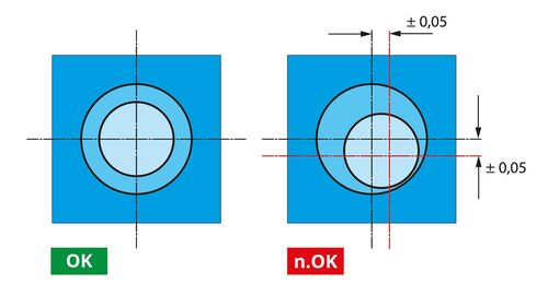
The customer requirements to be met by C-frames are generally based on specific criteria and tolerance limits that apply in automated production. In many cases, these quality standards even effect the process monitoring system that monitors and visualises the tolerances.
Example of clinching process:
Comments are disabled for this post.
0 Kommentar